Difficulty: More Difficult – Requires some soldering, building of a circuit.
The Problem
I want to put my Pi in my car to play movies and games, especially for long road trips. Actually, it’s for the kids to play games and watch movies…I’ll be driving. But…on long road trips we stop for gas. When we first turn the car off, we keep power as long as we keep the key in the ignition. But, when we restart the car, the ignition cuts power to the accessories, and Pi reboots. Movie stops playing, loses its place, or game restarts. 🙁 So sad! What to do about it?
I want a very short lived power supply for the Pi. Really, it doesn’t have to last more than a few seconds, just long enough for the engine to crank, but let’s go ahead and make it last long enough that we can also go inside and grab a drink without the pi having to shut down.
Options (Tried and Failed)
- Just put a dumb UPS in the car. Well, I really thought this was a good idea and I had a spare sitting around. The problem is that the UPS needs 120V. Car runs on 12V. To get the 12V to 120V, I needed to use an inverter, but the inverter doesn’t produce a good clean signal for the UPS (because it’s trying to make it from 12V). My end result was that the UPS didn’t charge while plugged in, but produced a piercing alarm which made driving really obnoxious. Plus, the UPS is kind of expensive and I didn’t get to build it.
- OK, so spare UPS doesn’t work, how about a simple USB power bank. It charges when plugged in and delivers 5V, sometimes up to 2A to charge a cell phone. PERFECT! But…the ones I tried could only be charging or discharging at any given time. I’d like to say that I only tried one…but that would have been too simple. The point is, I think this is a widespread problem with power banks. I’ll explain why that is later, but the point is this doesn’t work. If I always have the Pi plugged in, eventually the battery discharges and the Pi dies, even when the charger is plugged in. Well, that’s pretty much the opposite of what I wanted.
So, how can we do it?
What I really want is a UPS in the car. But, you can’t really use a UPS with the inverter in the car because the input voltage isn’t clean enough. OK, so I want a UPS, able to output at 5V, with input from a 5V source, that works in the car. I’ll have to make one.
Some things to keep in mind:
- It’s easy to find a USB wall converter that outputs about 5V
- Lithium Polymer batteries are pretty easy to come by, are rechargeable, relatively cheap, and available in a bunch of capacities
- Lithium Polymer batteries operate around 3.3 V (both charge and discharge)
- 3.3 V < 5 V: This causes some problems. I can’t really charge the LiPo battery at 5V, I’d kill it or myself. I also can’t run the Pi off 3.3V, it’s not strong enough.
So, here’s the basic idea:
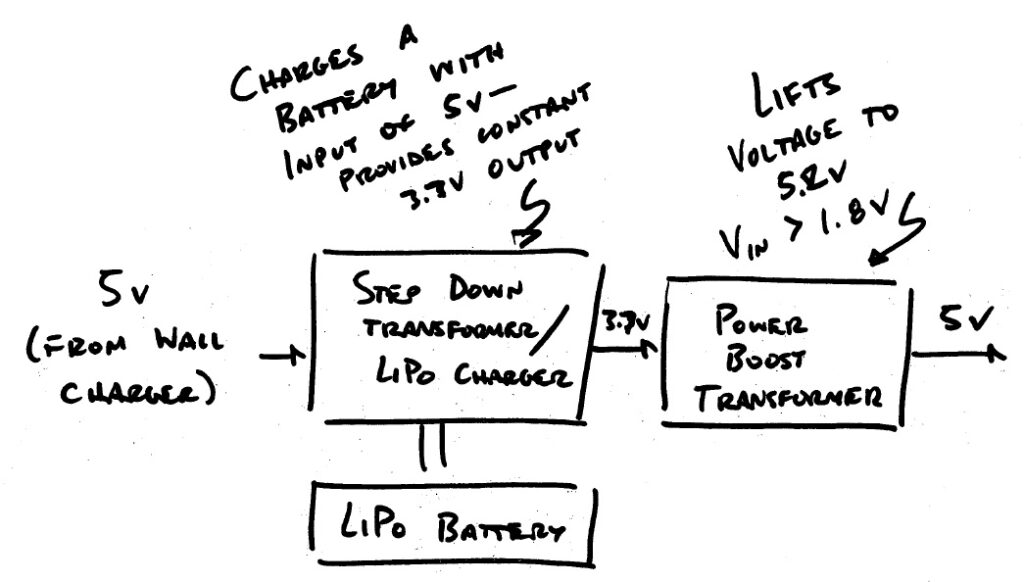
Basically, I take the 5v input from the wall (a standard USB charging adapter), and use that to charge a Lithium battery, using a handy charging circuit like the one available at Adafruit.com here. The LiPoly charger takes a 5V input, at the DC In Terminal and connects to a standard battery, either using the included plug, or by wiring directly into the Batt terminal. It also provides a steady 3.7V output. When the charger is plugged in, this is pretty much a pass through from the output of the transformer. When the charger is unplugged, it is power from the battery. For my project, I used the 1200mAh battery shown here. When the circuit is powered and the battery is not fully charged, the battery will charge. The charging circuit logic automatically stops feeding the battery juice once it’s fully charged.
In either case, power is first dropped to 3.7V using a buck beak transformer. The output will be a steady 3.7V, until power is unplugged AND the battery is discharged. This is better, but I still need 5V to run the Pi.
Side Note: Remember that comment about the Power Banks not working? I think this is why. A buck beak transformer is needed to bring the power down from 5V to 3.7, and then a second to bring it back to 5V. The same transformer can be used (depending on which side you define and input vs. output), but power can only go one way at a time. Power bank makers save money by including only one transformer. When it’s in charging mode, the 5V supply is fed to the input, and the 3.7V output is used to charge the battery. When it is discharging, the whole thing is reversed, and the 3.7V output from the battery is fed back through the transformer to give you 5V to charge your phone. The problem is, it can’t do both at once with only one transformer!
Once I have the steady 3.7V output, I run the output from the charger through a power boost transformer (also from Adafruit) to get a steady 5.2 V output, regardless of whether I am plugged in or not.
Programming the Charger
Remember, the Pi is going to need power. I use mine as a media server with an attached hard drive. So…I don’t really want too much of my 2A supply going to charging the battery, it won’t leave anything left to run the Pi. I need to limit the charging current. You can do this with the program terminal on the charging board. (Labeled PROG). I used an approximately 5K resistor to limit how much current the charging circuit draws.
Control where power comes from
The charging circuit is only designed to support up to 1A. I don’t really want all power flowing to the Pi to have to come from the charger, there won’t be anything left to charge the battery. I tried this, the charging circuit overheats and stops functioning if the Pi draws too much power. So…I want to power the Pi directly from the plug, when power is plugged in.
You can’t just connect the supplies in parallel. If the voltages don’t match exactly (and it never does) power won’t be split evenly between the two supplies. Actually, one will likely supply all the power, and contribute power to the lower voltage supply. This is not a good thing! It’s called a short circuit. Even if nothing too bad happened, with my luck, the battery would supply all the power and would thus be dead when power was cut.
So, I designed a little circuit to help.
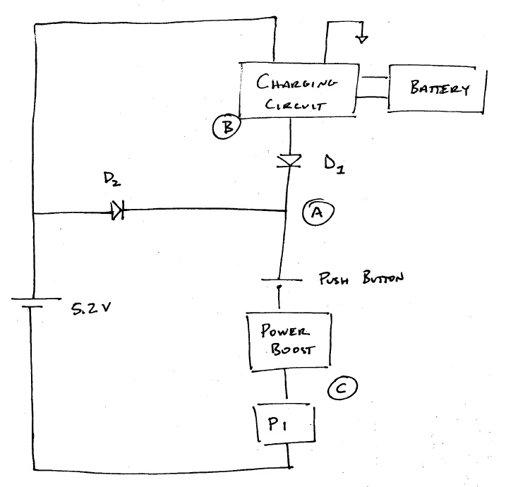
So, here’s how it works.
D2 → Prevents backfeeding of 5v wall transformer when power unplugged and battery supplying circuit
D1 → Acts as a Switch. When plugged in, VA ≈ 5.17v, VB=3.7v. D1 is reverse biased and battery will not energize circuit (But will Charge). When unplugged, power will flow through D1. VA ≈ 3.4v which is high enough for power boost. VC always ≈ 5.2v.
By using a couple of well placed diodes, power is always supplied by the wall if power is plugged in. The Pi is powered and the battery is charging (until fully charged thanks to the charging circuit). Once power is cut, all power is supplied from the battery.
That’s it! Now you have a 5V Uninterruptable Power Supply that you built yourself to power the Pi even when power goes down. The length of time will depend on the capacity of your battery and how much power your Pi is drawing.